Solved with BIM: Using Clash Detection to Solve Exterior Design Issues (a case study)
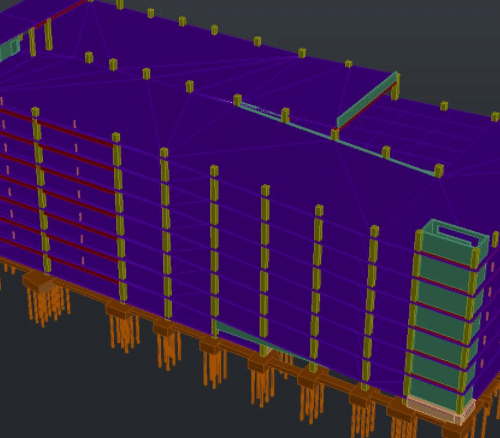
BIM is not just for your glazing projects; it can be an amazing tool for any component of the building cladding systems. This case study involves a parking deck with post-tension cables and decorative metal fins on the building exterior. The post-tension cables are of course an important feature because they allow for thinner concrete slabs and greater span lengths between support columns, which leaves more room for parking. The negative side of this design, however, is that no part of the building enclosure system can be fastened in the same space where the cable or its ends exist. The image below shows the BIM model for this building without the decorative components that we were responsible for.

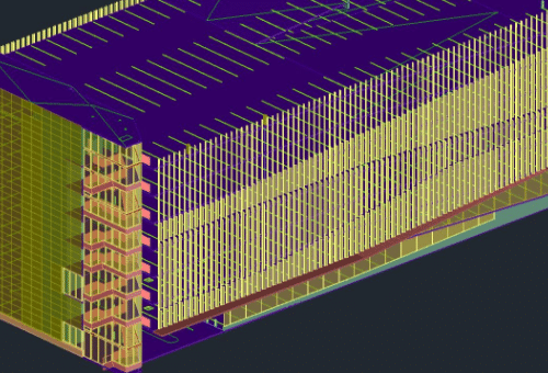
The most critical architectural design feature is the decorative metal fins attached to each floor line of the structure. As you can see from the image below, there were thousands of connection points for these fins. The sheer volume presented a real challenge. Through clash detection exercises utilizing AutoCAD, Revit, and Navisworks, we discovered that hundreds of the proposed metal fins in the original design would be in direct competition for space with the post-tension cable ends. These interferences would have been very difficult to discover without a 3D BIM model. This is just one way BIM reduces the probability of human error.

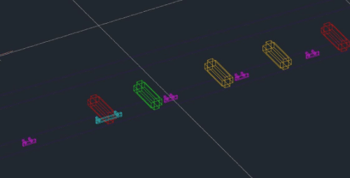
The next image gives you an idea of the challenge we needed to work through. The light blue anchor is a modified version of the typical application, designed to span over the end of the cable and prevent obstruction with the metal fins. Once we solved this interference problem conceptually, we were able to apply a unique solution for each area, as varying issues required different strategies. Because we utilized embeds on this project, we were able to move the embeds, add extra, and/or span them across the cable ends. We made sure the fins kept their designed spacing, even though their attachment points had to be modified, which allowed the finished product to look exactly like the architect intended.

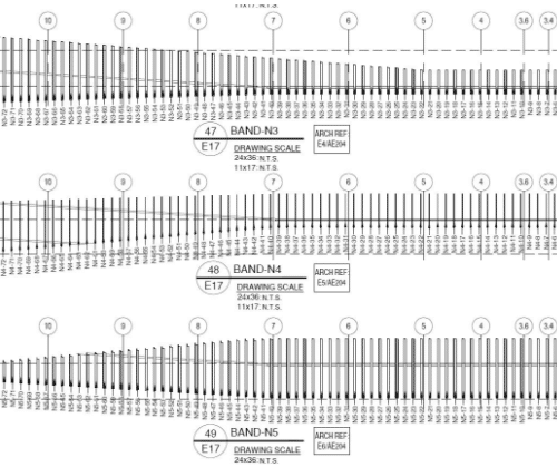
Finally, with the anchors worked out, we were free to place and model the individual fins as designed by the project architect. The next step was to create the shop drawings, utilizing the information gained from the BIM model. The image below shows elevations of the decorative fins from the shop drawings.

This project is a great example of what a skilled drafting team can accomplish with 3D modeling technology. It shows the clear benefit of using 3D BIM for complex designs in order to identify and solve any interferences early on in a project. If you’re working on a similar project and need help integrating decorative metal features into the design, we would love to hear from you.

